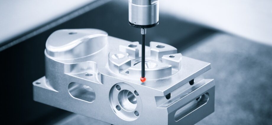
A feature can look simple on a drawing yet become difficult to inspect once surrounding geometry limits your approach. You may have enough reach to touch the target surface, but that doesn’t guarantee the probe can approach at a useful angle with adequate clearance. Planning probe angles for hard-to-reach features requires you to consider the entire movement toward the measurement point. This helps you choose orientations that provide practical access while supporting a reliable inspection routine.
Look Beyond the Target Point
When you plan a probe position, it’s easy to focus on whether the stylus tip can reach the measurement point. However, the rest of the assembly still needs room to move. A shaft may pass close to a wall as the probe head moves toward the target, turning a seemingly accessible feature into a difficult one.
Think about the complete path from the probe’s starting position to contact. You need enough clearance for the stylus to reach the surface without bringing the rest of the probe too close to the part. Considering the entire movement gives you a clearer picture of access than focusing on the final contact point alone.
Match Direction to the Surface
Once you know the probe can physically reach the area, consider the direction of contact. Choose an approach that suits the surface you intend to measure while giving the probe a clear path to the correct location.
Complex geometry makes this relationship especially important. An angled wall inside a pocket may require a different probe orientation from a nearby surface, although both features occupy the same small area. If you use the same approach simply because it reaches both locations, you may overlook the direction each measurement requires.
Account for Nearby Geometry
Deep pockets and recessed surfaces often leave little room around the probe. As you change the head angle, another part of the assembly may move closer to the workpiece. Review clearance with the probe in its intended measurement orientation. Consider more than the space immediately around the stylus tip.
A probe can clear the target at contact while another section of the assembly passes too close to an edge during the approach. Reviewing the complete configuration helps you identify these conflicts early enough to adjust the routine. A practical clearance review should answer a few focused questions:
- Can the stylus reach the target without contacting nearby geometry?
- Does the shaft have enough room throughout the approach?
- Can the probe head rotate safely into the required position?
- Does the withdrawal path remain clear after measurement?
Understand Five-Axis Direction
Five-axis measurement gives you additional freedom because the probe head can change orientation as part of the inspection process. However, that flexibility also increases the importance of accurate directional information. As the head changes angle, the inspection program needs accurate information about the stylus orientation and intended measurement direction.
Probe vectors provide a way to describe that direction within the coordinate system. Understanding vector group calculations for five-axis probe heads can clarify the relationship between head orientation and the stylus direction at each measurement position. Connecting those values to probe movement can help you interpret what each programmed orientation represents.
Consider the Full Configuration
Consider your chosen angle as part of the complete probe configuration. If you change the stylus arrangement, the same head position may no longer provide the clearance you expected. A longer assembly can reach farther into a recess, but the added length also changes the clearance available during the approach.
You should revisit the planned angle whenever the physical setup changes. Look at where the contact element sits relative to the head at the selected orientation. Reviewing the current configuration helps you avoid relying on an angle chosen for a different setup.
Check Qualification and Orientation
You also need to confirm that each probe orientation corresponds with the qualification information required by your CMM and probe system. Depending on the equipment, you may need qualification data associated with specific positions, while other systems can manage additional orientations through their own procedures. Follow the applicable equipment instructions when you establish or change probe positions.
Pay particular attention when you revise an existing inspection routine. A new angle may solve an access problem, but you still need to confirm that the system has the appropriate information for that configuration. Confirming the required qualification information helps you avoid assuming that a mechanically accessible position is ready for measurement.
Review Motion Before Measurement
A probe position may appear suitable when you consider only its final location. The route into that position may reveal a different problem. For that reason, review the approach and withdrawal motion before you rely on the new angle during inspection.
Simulation can help when your CMM software supports it, particularly around deep or obstructed features. Still, compare the planned movement with the actual part setup. Fixtures or other physical constraints may affect the usable space around the workpiece.
When you change an angle, review the surrounding moves as well. The probe may need to travel from a previous feature at a very different orientation, so a safe measurement position still needs a practical transition. Reviewing that transition helps you maintain a practical path from one measurement to the next.
Make Difficult Access More Predictable
Complex geometry doesn’t always require the most complicated probe angle available. Often, a better approach begins with identifying what prevents straightforward access. Once you identify the obstruction, you can choose an orientation that addresses that constraint.
As you gain experience planning probe angles for hard-to-reach features, treat each position as part of a larger movement through the workpiece. Check the available clearance during the approach, then review the withdrawal path after contact. That perspective can turn difficult access from a trial-and-error problem into a more deliberate programming decision.
The next time a recessed or obstructed feature challenges your inspection plan, study the space around it before committing to an angle. Consider the path the probe needs to follow and verify that the selected orientation supports the intended measurement. Careful planning gives you a stronger foundation for handling other difficult features as inspection requirements change.
Check out: What’s the Difference Between Regular Printers and Plotters?